What is PLC | PLC Tutorial | Programmable Logic Controller
- PLC or Programmable Logic Controller may be a computer system for the Automation Industry. it's a special-purpose computer without a keyboard, disk drive , etc. PLC is one among the demanding skills of the Electrical industry. Most organizations require a candidate having knowledge of PLC. Here, we'll discuss Automation, applications, types, programming, process, architecture, etc.
PLC
What is PLC ?
- PLC is a computer system adapted to control the robotic devices and other manufacturing processes.
- It involves a basic study of Microcontrollers , digital circuits, and designing skills.
- It provides easy, flexible, high-reliability programmable controllers suitable for easy and harsh environments. It monitors the state of input devices, takes decisions, and controls the output devices.
- The applications include Robotics, water filling tanks, etc.
- PLC ranges from small devices with few Input/Outputs to large devices with thousands of Input/Outputs.
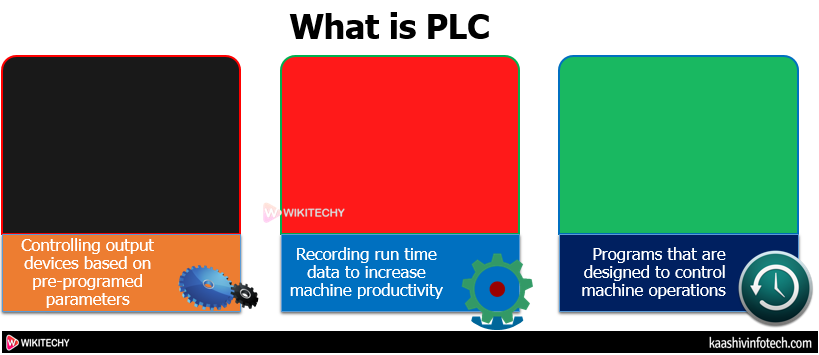
What is PLC
Why PLC ?
- PLC was initially created in the US for the replacement of relay systems.
- The drawbacks of relays that make them unsuitable for the automotive industry are listed below:
- The computer operation using relays logic was quite challenging and time-consuming. A change within the logic of the machine makes the method complicated.
- Relays also fail quickly compared to computer components.
- It requires more run downtime.
- Relay also consumes plentiful electricity, more space , and heat. Hence, to beat such drawbacks, PLC was created.
- A PLC model features a simple appearance. The CPU (Control Processing Unit) communicates with the Input/output. The I/O modules could also be present near or farther faraway from the CPU.
- Hence, PLC isn't limited to at least one building. It includes calculation within the programming, which is used to calculate different parameters, like SPC (Statistical Process Control).
- But for its operation, we'd like to program the Programmable Logic Controller. Most PLCs are controlled using the applications on the desktop/laptop.
- These applications communicate with the PLC using the communication medium, like Ethernet or the proprietary communication bus. The choice of communication medium depends on the manufacturer. Most manufactures also believe the USB.
- The specific logic is different for every programmer with different techniques of doing the same thing.
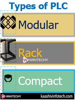
Types of PLC
- Three types of PLC, which are shown below:
- Modular PLC
- Rack PLC
- Compact PLC
Types of PLC
Modular PLC
- In modular PLC, modular means adding modules. It allows us to expand the structure of PLC. It's useful when there are an outsized number of inputs and outputs. We will add more input and outputs by adding the modules within the PLC.
- It also has more memory and capability to store information.
- The example includes control processing lines within the manufacturing industry.
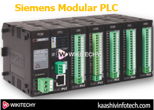
Siemens Modular PLC
Rack PLC
- The modules within the rack type PLC are arranged within the rows. The racks are placed inside the cabinets . The slots within the rack PLC communicate with one another connected by the standard network or bus.
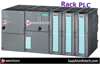
Rack PLC
Compact PLC
- The Input / Output (I/O) modules within the compact PLC are determined by the manufacturer of that PLC. It means the I/O is fixed. But, the compact PLCs are used for little scale applications.
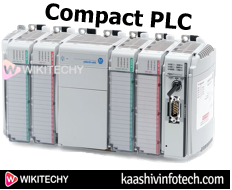
Compact PLC
How PLC works
- PLC takes the input from the input devices, processes it depends on the logic within the CPU, and controls the output devices based on that logic.
- PLC is lightweight and may operate without any air conditioning or electrical filtering.
The devices like pushbutton, sensors are connected as the input devices, which may detect a change in the input signals in the PLC. The input passes through the barrier that converts the voltage into low voltage, like 5V. The CPU monitors the state of the input. Based on the required logic, CPU processes and produces the output .
The barrier present at the output terminal prevents the PLC from external noise and converts the low voltage to high voltage to drive output devices. The output controls the output devices, like motor, controllers, pilot lights, etc.
Architecture of PLC
- The PLC hardware setup or architecture contains the hardware and software that is used to perform the control functions.
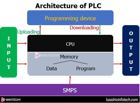
Architecture
Components of the PLC
PS
- PS stands for Power Supply. the facility supply acts as an power source for the PLC system. It converts the high voltage into low voltage or DC, like 120V AC to 24V DC.
- The Linear power supply is a smaller amount complicated than the other modes of power supply.
SMPS
- It stands for Switch Mode Power Supply. SMPS is power conversion and a high-frequency power conversion device. It converts the voltage level into the specifically required voltage. SMPS uses solid stat switches to convert the AC supply into the DC supply.
- SMPS is usually used for top power conversion from AC to DC. It also has high efficiency than PS.
Differences between PS and SMPS. Consider the below table.
| Category | PS (Power Supply) | SMPS (Switch Mode Power Supply) |
|---|---|---|
| Weight | Bulky | Light in weight |
| Efficiency | Low efficiency between 20 % to 25% | High efficiency between 60 % to 65% |
| Complexity | Less complex | More complex |
| Response | Faster response | Slower response |
| Uses | Radio frequency applications | Mobile chargers, DC motors, etc. |
Read Also
How SMPS Converts Voltage ?
- Consider he AC voltage of 224V. The process will convert 224V AC to 24V DC.
Block diagram
- It clearly explains the process of converting high voltage to low DC voltage.
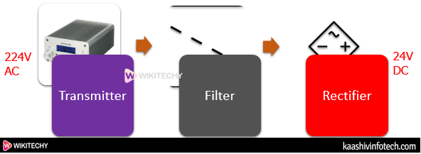
Block Diagram
CPU
- CPU or Central Processing Unit is present within the Central rack of the PLC. The data bus is used as a medium to send data between different elements within the PLC. It controls all functions, like programmed instructions stored within the memory of PLC. It also controls logic, communications, and monitoring within the PLC. It's the unit of the PLC that contains a microcontroller or microprocessor.
- The CPU executes the program when it's operated within the run mode.
IM
- IM or Interface Module is defined as an accurate, position sensing, and absolute device. It's commonly used with transducers to reduce noise in harsh environments.
Programming device
- We need to specify the specified program into the processor's memory. The program is initially developed within the programming device. then , the program is transferred to the memory unit of the PLC.
CP
- CP stands for Communication Process. The communication process in PLC includes a wiring system and a shared protocol. The wiring system is used to connect different components in PLC, whereas shared protocol allows any device to know the bits and bytes within the communication process.
MCB
- MCB or Miniature Circuit breaker acts as a security device for the PLC. It automatically switches off the circuit if an overload or fault condition arises. MCB is generally used instead of fuse I low voltage electrical network.
Input Module
- The input module of PLC detects the input devices' status, like sensors, switches, push-buttons, etc.
Output Module
- The Output module of PLC controls the output devices, like motors, relays, lights, etc.
Rack
- The Rack usually acts as a device of PLC. It means it holds everything together. we will add racks within the PLC to hold more modules. The racks also are available in a different size.
Memory Unit
- Memory Unit is that the unit that stores programs, data, and information within the PLC.
- The PLC has two sorts of the memory unit, which are listed below:
- Data Memory : The data memory consists of the stored data from the Input/output modules of the PLC.
- Program Memory : The program memory consists of the logic program or ladder logic program within the PLC.
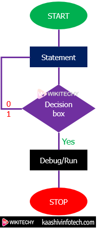
PLC Cycle
- The PLC system is usually expensive. The incorrect programming or design of PLC may result in loss of productivity.
- To save lots of the time to design of PLC control applications, simulation software like PLCLogix are recommended. Such software saves time and also increases the security related to the PLC equipment.
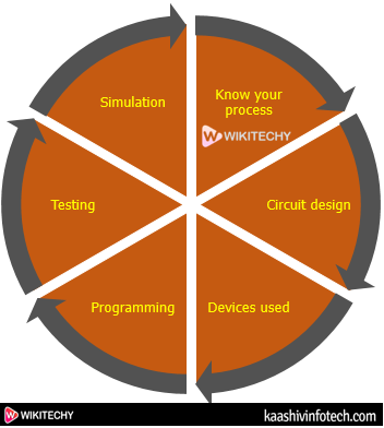
PLC Cycle
- Know your Process :
- We should always know our process that we are starting with.
- Circuit Design :
- The planning is that the first a part of any project. A project or model can't be created without design.
- Devices used :
- It's crucial to understand the devices used in the project.
- Programming :
- It's an important part. The created model is programmed for implementation.
- Testing or Simulation:
- At the last stage, the model is tested. Considerable time is spent on testing and simulation.
The above steps are necessary to know the operation of the PLC.
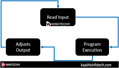
Scan cycle of PLC
- The PLC continuously scans the method because the inputs are random. The scan cycle is split into three parts, named Input scan, Output scan, and program execution.
- Scan time :
- It's defined as the time taken by one cycle to travel through the program. The time duration of a cycle is minimal, i.e., 1/1000th of a second. It can vary depending on the program.
- The lesser the scan time, the higher and expensive are going to be the PLC.
Scan Cycle
- Input Scan :
- The PLC solves the logic supported the required inputs.
- The ON/OFF state of the input is saved in the data table in advance , avoiding sudden changes within the input. It also makes the method faster.
- Program Execution :
- The control logic keeps the memory copy of the ladder logic program. It executes just one instruction at a time using that copy .
- Output Scan :
- It updates the outputs after the scan process is completed.
- The values of the program are temporary. Based on such values, the Output is updated. then , it self-checks for any fault and restarts the method .
What is a Safety PLC ?
- The safety PLC is similar to the normal PLC with some extra safety features, like redundancy. The safety PLC also can perform additional field device checking, like snooping.
- The PLCs are a part of the Automation System, which is said to EE (Electrical engineering). A security PLC is one of the important of any automated process.
- The sensors, PLC (logic solver), and therefore the control systems are considered the three parts of the SIS (Safety Instrumented System). SIS is termed as Safety Shutdown System.
- The SIS monitors a process and reacts by making a shutdown if any unsafe or risk condition arises.
- The role of safe PLCs is to protect the method against project/plant failures to prevent the environment from harsh risks. In any hazardous condition, safety place will place the plant during a safe condition.
What is Automation ?
- Automation is defined as a process, system, procedure that reduces human efforts to a minimum. It's a robot that operates and functions automatically without continuous input. The devices are created electronically.
- The scope of Automation is increasing like other technologies, like Machine Learning and Artificial Intelligence. For eg , aircraft, boilers, heat treating ovens, automatic machinery, etc.
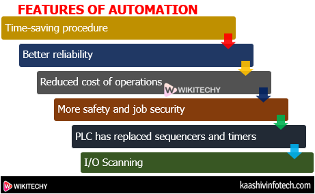
Features of Automation
- Automation has not only reduced human labor but also uses machinery for repetitive tasks.
- Industrial Automation has resulted in increased productivity, safety, better utilization of resources, improved production rate, and better output.
- It has increased consistency.
- Time-saving procedure.
- Better reliability
- Reduced cost of operations.
- More safety and job security.
- PLC has replaced sequencers and timers.
- I/O Scanning
Features of Automation
- The automation is categorized as Industrial and Non-Industrial Automation.
- Industrial - PLC, SCADA, HMI, VFD, RTO, DCS. It uses waterfilling, Robotics machine, Tanic , Printing machine, Panels(HT, LT, PLC).
- Non Industrial - It is used for security purpose, Civil and Banking.
Types of Automation
- Fixed Automation
- Flexible Automation
- Programmable Automation
- Integrated Automation
Fixed Automation
- Fixed automation has an open and logic-based programming system. But, it's a high production rate and high initial investment.
Flexible Automation
- The flexible automation is quite flexible in handling the products having design variations.
Programmable Automation
- It is a human-based system. Here, the new program is prepared and enters into the new equipment to make new products.
Integrated Automation
- It is the mixture of the above three automation (fixed, flexible, and programmable).
- It's an industrial system that extends its technical services within the engineering domain.
Applications of PLC
- We generally use a desktop or laptop for programming.
- Some of the applications of PLC are listed below:
- Controlling elevators
- Controlling traffic signals
- Washing machines
- Amusement rides
- Machinery control
- Bottle filling system
- Water tank level control
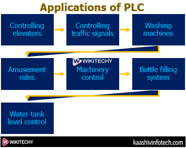
Applications of PLC
Criteria for Choosing PLC
It is essential to pick the simplest PLC. Let's discuss the criteria for choosing a PLC.
We should always select any PLC based on the following parameters.
System Requirements
- The required PLC should be compatible with the system requirements of our computer or laptop.
- We should always check the PLC model.
Scan time
- It is also an important a part of selecting any PLC. The PLC will less scan time is considered as the best PLC, but are costly. The variation of scan time depends on the amount of inputs of the PLC.
Communication
- Communication means sharing information with other devices. The hardware cable are often twisted pair cables, radio modem, etc.
Speed of Operation
- It defines the operating speed of the system of the PLC.
Application Requirements
- It determines the input and output requirements for the PLC system.
Electrical Requirements
- The Electrical requirements include the parameters, like input voltage, control system's power, output current, and output voltage.
I/Os
- The I/O modules should be selected according to the specified project needs. If we would like to control the stepper motor, we will choose a Rack PLC.
Memory
- We need first to see the specified amount and size of the memory. The memory of the PLC is related to the amount of I/O, the installation of the control program, etc.
Software Requirements
- The software requirements include compatible CPU, Communication and I/O ports, USB port, Ethernet port, user-specified port, etc.
Physical Requirements
- We should always consider the situation of the PLC system .we should always place the PLC system in IP-rated closure within the harsh environments. Other parameters, like maintenance, accessibility, and troubleshooting, should even be kept in mind before selecting any PLC.
Siemens PLC
- Siemens PLC is the common PLCs used everywhere the industries.
- The Siemens PLC are divided into three generations, which are given below:
- 1st Generation - Micro
- 2nd Generation - Mini
- 3rd Generation - Nano or Rack PLC
- The series of Siemens PLCs are listed below:
- S7200
- S7300
- S7400
- S7400H
- S7400F
- S71200
- S71500
- S7400F PLC also has the feature of Fault Tolerance. we will select the product as per the need .
- S7200 is that the cheapest available Siemens PLC. It's easy to start out programming with the S7-200 PLC.
SIMATIC STEP 7
- Simatic step 7 is that the powerful automation software tool, which incorporates the programming environments for Siemens PLCs.
- The Simatic Step 7 engineering software are often used for programming and configuring HMI Basic Panels.
- The supported programming languages within the STEP 7 software are ladder programming, Functional diagram , and Structured text programing language. Today, the intelligent choice for automatic is that the SIMATIC S7-1200 controllers.
- The benefits of S7-1200 controllers, which are listed below:
- These PLCs are available in failsafe and standard versions.
- It comes with extended communication functions and improved data transfer.
- It allows the transfer of sensitive machine data.
- It supports predictive maintenance.
- It also supports data transfer with other controllers.
- It enables data storage.
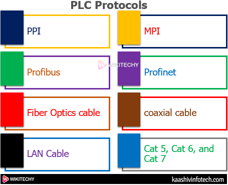
PLC Protocols
- PLCs communicate using the protocols. The protocols related to the PLCs are listed below:
PLC Protocals
PPI
- The PPI or Point to Point Interface Protocol may be a communication protocol specially designed for S7-200 PLC. But, it's indirectly opened by Siemens.
MPI
- The MPI or Multi-Point Interface Protocol is an interface of the Siemens Company. The MPI is used to connect the devices, like personal computers, etc. The speed of MPI ranges from 187.5 kBd (Kilo Baud) to 12 Mega Baud.
Profibus
- Process field Bus or Profibus uses a multi-drop single cable, which is used to connect the devices. It's often confused with the Profinet. It's easy to seek out faults during a single cable. The installation cost of the Profibus cable is very low.
Profinet
- The Process filed net or Profinet is additionally used by Siemens like Profibus. The response time of Profinet is quicker , which provides higher data collection.
Fiber Optics cable
- The Fiber Optics cable supports high bandwidths level and high transmission capacity over long distances.
Coaxial cable
- The coaxial cable acts as a wired transmission intermediate between the devices. Ethernet cables are considered for wiring analog input and outputs in PLC. The Ethernet connection provides faster security and reliability than the wireless connection.
LAN Cable
- The LAN cable provides the downloading and uploading capacity from the host computer to the PLC. The common LAN applications include distributed control, etc.
Cat 5, Cat 6, and Cat 7
- Cat stands for Category. These are the common Ethernet standards that are widely used for transmission with reduced interference.
- The speed of Cat5 is upto 100Mbps.
- The speed of Cat6 is upto 10Gbps.
- The speed of Cat7 is upto 100Gbps. It's the newest cable, which is shielded.
Twisted Pair cables
- It is a type of wiring system in which two pairs of conductors of single circuit are twisted together to enhance the electromagnetic capability of the circuit.
PLC Manufacturers
The industries that make PLC are listed below:
Siemens
- It is the German multinational company that manufactures PLC. It's documented and most used PLC all over the world.
Rockwell Automation
- It is an American company that also took over the Allen Bradley brand. It's the most important manufacturer of PLCs and well known in the US.
ABB
- The ABB may be a Swiss multinational company that gives PLCs within vast industries and applications.
Omron
- It is a Japan-based company .
General Elastic
- It is an American based PLC company.
Delta
- It deals with all kinds of automation machines. It's a Taiwan- based PLC manufacturer.
Schneider
- The Schneider may be a French-based PLCs manufacturer.
Mitsubishi
- It is a Japanese MNC group that manufactures PLC.
Koyo Electronics Corporation Limited
- It manufactures the DirectLogic PLC brand. It's a Japanese based industry.
PLC Programming
- PLC programming may be a crucial task of implementing and designing control applications as per the user requirements. It's the set of instructions which will be within the graphical or textual form.
- The most commonly used method called Ladder diagram, which may be a sort of graphical method. The PLC works according to the required program as soon because it is placed within the run mode.
- The programming is administered within the PLC software. Here, we've discussed the software that's popularly used for Siemens PLC called SIMATIC STEP 7. Easily download it from any browser. The function blocks within the programming include push-button, counters, timers, comparators, etc.
Types
- We have discussed that the control logic establishes the input and output of a PLC. The control logic of the PLC are often programmed using different programming languages.
- Out of all the programming languages, Ladder is that the common programing language used for PLC.
- The initial version of IEC standard 61131-3 supports five basic programming languages called FBD, ST, IL, SFC, and Ladder. The standard-based programing language to program PLC is named the Ladder diagram. ST and IL are the textual programing language , while Ladder, FBD, and SFC are the graphical programming languages.
Let's discuss six types of programing language , which are listed below:
FBD (Function Block Diagram)
- The functions within the FBD diagram are described as the set of elementary blocks. The variables (input and output) within the Function diagram are connected to blocks by the lines.
ST (Structured Text)
- The Structured Text may be a block-structured language that's supported Pascal. It's a application-oriented language. It's also a text-based language.
IL (Instruction List)
- The instruction List may be a text-based and a low-level language.
SFC (Sequential Flow Chart)
- The Sequential Flow charts are defined by the function of charts during a sequence. we will use it if the method are often divided into steps.
Sample Program
Sample Program
Ladder Logic
- It is defined as a graphical programming language that uses symbolic notation for expressing the logical operations. We will program the PLC on any software using the ladder logic.
Before beginning with the programming, let's discuss some basic concepts.
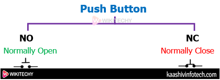
Push Buttons
- The pushbuttons are the simple buttons to control the machine or a process. We are required to push the button to vary its electrical state from ON to OFF or vice-versa.
- Push buttons are further categorized as NO (Normally Open) and NC (Normally Closed), as shown below:
- NC : The Normally Close is that the default state of a circuit that creates electrical contact with the circuit. It means the circuit is in ON state.
- NO : The Normally Open is that the state of a circuit that creates no electrical contact with the circuit. It means the circuit is within the OFF state. It opens the terminal of the circuit to interrupt the flowing current.
- We will use pushbuttons for programming in PLC.
Push Button
Symbols Used in Programming
- Various symbols are used to create a ladder circuit for PLC programming. Let's consider some essential symbols.
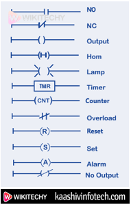
Symbols
- The concept of NO and NC. we'll also discuss the output of NO and NC buttons when the input is 0 or 1.
NO
- The NO button turns NC when it's pressed. It means, when the input is 1, NO turns NC. It means the present can undergo .

NO
- It clearly shows that when the input is 0, NO remains NO. It turns NC when the input is 1.
NC
- The NC button remains an equivalent when the input is 0. It turns NO when the input is 1.

NC
- We can arrange NO and NC in parallel or series according to the needs.
- Now, we'll discuss the logic gates with their ladder diagram. The concept of using NO and NC during a ladder diagram will help us in building the circuits of PLC.
The ladder diagram of Logic gates are discussed below:
Logic Gates
- We will discuss logic gates with their circuit using NO and NC buttons.
Basic Gates
- The Basic Gates are AND, OR, and NOT.
The truth table of OR and AND circuit is given below
| A | B | OR | AND |
|---|---|---|---|
| 0 | 0 | 0 | 0 |
| 0 | 1 | 1 | 0 |
| 1 | 0 | 1 | 0 |
| 1 | 1 | 1 | 1 |
The truth table of NOT Gate is given below:
| A | NOT |
|---|---|
| 0 | 1 |
| 1 | 0 |
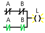
Ladder Diagram of AND circuit
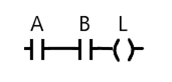
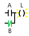
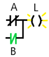
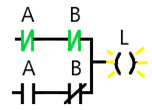
The ladder diagram of AND circuit is given below:
Ladder Diagram of AND circuit
- Here, A and B are the inputs, while L is that the lamp. The lamp will glow when the current flows through the circuit and reaches the lamp. Otherwise, the lamp won't glow.
- When A = 0 and B = 1, the circuit will appear as:
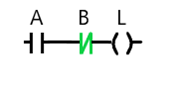
Ladder Diagram of AND circuit
- The lamp will not light because the starting button is OFF. The current will not flow.
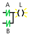
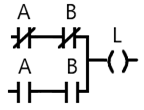
- But, if A = 1 and B = 1, the circuit will appear as:
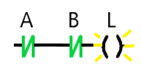
Ladder Diagram of AND circuit
- Here, the lamp will light. Hence, the condition of the AND circuit is satisfied.
Similarly, we'll create a ladder diagram for all the gates using an equivalent logic, as discussed above.
Ladder Diagram of OR circuit
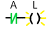
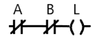
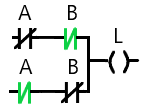
The ladder diagram of OR circuit is given below:
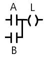
Ladder Diagram of OR circuit
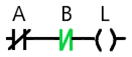
- When A = 0 and B = 1, the circuit will appear as:
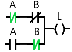
Ladder Diagram of OR Circuit
- When A = 1 and B = 1, the circuit will appear as:
Ladder Diagram of NOT Circuit
Ladder Diagram of NOT Gate
- The ladder diagram of NOT gate may be a simple NC.
- It will give output 1 if the input is 0 and vice versa.

Ladder Diagram of NOT Circuit
- If the input is 0, the circuit will appear as:
Ladder Diagram of NOT Circuit
- If the input is 1, the circuit will appear as:

Ladder Diagram of NOT Circuit
- The lamp won't light because NC will become NO.
Universal Gates
- The Universal Gates are NAND and NOR.
The truth table of NAND and NOR gate is given below:
| A | B | NOR | NAND |
|---|---|---|---|
| 0 | 0 | 1 | 1 |
| 0 | 1 | 0 | 1 |
| 1 | 0 | 0 | 1 |
| 1 | 1 | 0 | 0 |
Ladder Diagram of NAND Circuit
The ladder diagram of NAND circuit is given below:
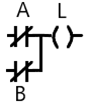
Ladder Diagram of NAND Circuit
- When, A = 1 and B = 0, the circuit will appear as:
Ladder Diagram of NAND Circuit
- Here, the lamp will light.
- If A = 1 and B = 1, the lamp won't light because both NC will become NO. Hence, the condition is satisfied.
Ladder Diagram of NOR Gate
The ladder diagram of NOR Gate is given below:
Ladder Diagram of NOT Circuit
- When, A = 1 and B = 0, the circuit will appear as:
Ladder Diagram of NOR Circuit
- Here, the lamp won't light because the primary NC will become NO.
- If A = 0 and B = 0, the lamp will light because both NC will remain the same. Hence, the condition is satisfied.
Exclusive Gates
- The Exclusive Gates are XOR and XNOR.
The truth table of EX-OR and EX-NOR gate is given below:
| A | B | XOR | XNOR |
|---|---|---|---|
| 0 | 0 | 0 | 1 |
| 0 | 1 | 1 | 0 |
| 1 | 0 | 1 | 0 |
| 1 | 1 | 0 | 1 |
For XOR
- Y= (A⨁B)
- Y= (A' B+AB')
For XNOR
- Y= (A⨁B)'
- Y= ((AB)'+AB)
Ladder Diagram of XOR circuit
The ladder diagram of XOR circuit is given below:
Ladder Diagram of XOR circuit
- When A = 0 and B = 1, the circuit will appear as:
Ladder Diagram of XOR circuit
- Here, the lamp will light.
- But, if A = 1 and B = 1, the circuit will appear as:
Ladder Diagram of XOR circuit
- Here, the lamp won't light because both the NC of the circuit becomes NO. Hence, the condition is satisfied.
Ladder Diagram of XNOR Gate
The ladder diagram of XNOR Gate is given below:
Ladder Diagram of XNOR Gate
When A = 0 and B = 1, the circuit will appear as:
Ladder Diagram of XNOR Gate
- The lamp won't light. The circuit is incomplete for the current to flow.
- But, if A = 1 and B = 1, the circuit will appear as:
- Here, the lamp will light. Hence, the condition is satisfied.
Read Also
Memory Mapping in PLC
- The memory mapping in PLC is discussed below:
- 1 byte = 8 bits.
- 1 bit = 0 or 1
- 2 bytes = 2 x 8 = 16 bits = 1 word
- 4 bits = nibble
- 2 word = 32 bit = 4 byte = 8 nibble = 1 double word
- The memory is split into program, words, and discrete registers.
Program
- The program is created using functional blocks and symbols. The functional blocks, functions, and blocks are often programmed using five programming languages, as discussed above.
Words
- 1 word = 16 bits.
Discrete Registers
- The 1-bit registers which will be used as input are considered as discrete registers. The 16-bit registers which will be used as input are considered as Input register.
Consider the partial memory map for the PLCs, which is shown within the below table:
| File No. | File type | Addressing range |
|---|---|---|
| 0 | Output Image | O:0 to O:30 |
| 1 | Input | Image I:0 to I:30 |
| 2 | Status | S:0 to S:n |
| 3 | Binary | B3:0 to B3:255 |
| 4 | Timers | T4:0 to T4:255 |
| 5 | Counters | C5:0 to C5:255 |
| 6 | Control | R6:0 to R6:255 |
| 7 | Integer | N7:0 to N7:255 |
| 8 | Floating-point | F8:0 to F8:255 |
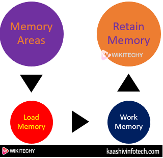
Memory Areas
- The Memory areas in PLC are categorized as Load Memory, Work memory, and Retentive memory.
Memory Areas
Load Memory
- It is a kind of non-volatile memory. It contains the memory and therefore the data blocks, code blocks, and therefore the configuration of the hardware.
Work Memory
- It is a kind of volatile memory. It contains the memory and therefore the data blocks. The work memory is only used in the CPU operation, and can't be extended.
Retentive Memory
- It is a kind of non-volatile memory. It saves a limited amount of data just in case of an power failure. But, certain actions like memory reset and factory settings reset can cause the deletion of memory objects of the retentive memory.
Other Components used in Programming
Other components used in the programming are listed below:
Timers
- The Timers in PLC provides the ON and OFF time delay like electronics relays. For eg, a timer of 5s is placed within the ladder circuit. The output are going to be OFF/ON after duration of 5 seconds.
The timers are categorized as ON timer, OFF timer, and Pulse timer.
ON Timer
- The output in ON timer is turned ON after the required delay. It's most commonly used in delay timer.
Memory Areas On Timer
- We can represent the time in two ways called seconds and milliseconds.
For example,
T # 5S_200MS
T#3S
Where,
S means seconds and MS means milliseconds
The parameters within the ON timer are listed below:
- Timer Number : File name
- Time Base : Time shown as a base. Here, it's shown in seconds
- Preset Value : Specified delay time
- Accumulated value : Value becomes 0 when the timer is reset. It starts the timer counting from 0.
The output of the ladder diagram is turned ON when accumulated time becomes equal to the Preset time.
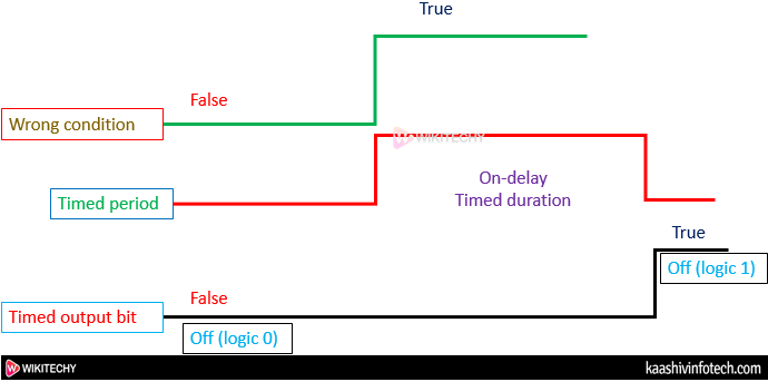
How ON timer works?
- When the condition or the logical diagram becomes true, the timer starts counting. It counts until the required delay time. For eg , if the delay time is 10 seconds, the timer will count upto 10 seconds. The counting appears within the accumulated value section. As soon because the value of the accumulated section becomes adequate to the Preset value (specified value), the logic operates (true) and turns the output ON.
Consider the below graph
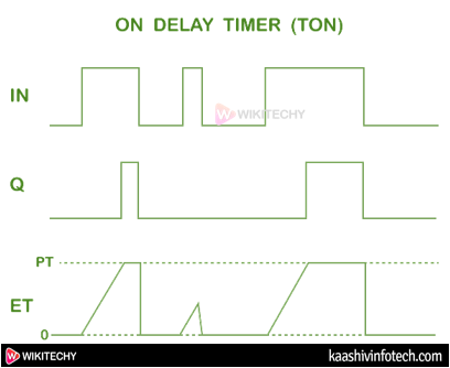
On Delay Timer
OFF Timer
- The output within the OFF timer is turned OFF after the required delay.
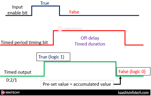
OFF Timer
- The parameters within the OFF timer are almost like the parameters of the ON timer.
- The output of the ladder diagram is turned OFF when the accumulated time becomes adequate to the Preset time.
How OFF timer works?
- When the condition or the logical diagram becomes true, the timer starts accumulating. It counts until the accumulated value becomes equal because the specified present value. As soon because the value of the accumulated section becomes adequate to the Preset value (specified value), the output becomes false and turns the output OFF.
Consider the below graph:
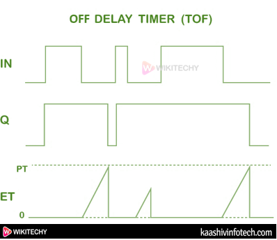
OFF Delay Timer
S_PULSE Timer
- The pulse timer is used to get pulses. It generated pulses of the required length.
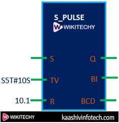
S_Pulse
- The parameters of the S_PULSE Timer are discussed below:
- S : It means SET. It's defined as the trigger signal of the timer.
- TV : It means the timer value stored within the timer. The value is represented as S5T#TV, where TV is that the specified value .
Let's consider an example
S5T#10S
Here,
10s is that the time specified in seconds.
R : It means RESET. It's defined as the reset signal of the timer.
Q : It's the output of the pulse timer.
BI : It represents the present time within the code.
BCD : It represents the present time within the binary coded decimal.
The time is specified in the form of S5T#5s.
Where,
5s is that the specified time in seconds.
To set the time as 10 seconds, we'll declare it as S5T#10s.
How does Pulse Timer work ?
- The set input (S) of the timer becomes active when it receives a positive pulse. The timer is in running state as long because the input is '1'. When the input changes its state from 0 to 1, the output is enabled. The timer keeps running until the accumulator value reaches the Preset value. we will read the accumulator value at the BI and BCD output of the pulse timer.
Consider the below graph
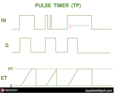
Pulse Timer
S_ODT
- Here, ODT stands for On Delay Timer. The timer runs as long as the input state of the signal is positive.
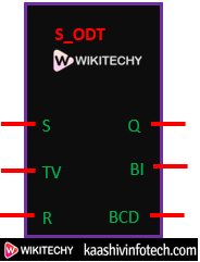
S_ODT
The parameters of the S_ODT timers are almost like the S_PULSE timers.
S-ODTS
- Here, ODTR stands for On Delay Timer. It's a kind of Retentive On-delay timer.
- The timer starts when the SET state of the timer is positive. The timer restarts when there's a change within the state from 0 to 1.
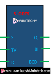
S_ODTS
Let's consider the graphs of S_PULSE, S_ODT, and S_ODTS timers, which are given below:
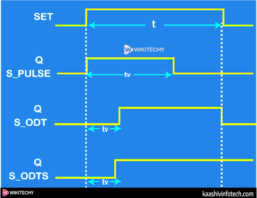
TV represents the Pulse
Counters
- The counters are categorized as Step-up, Step-down, and Step-up-down.
Step-up Counter
- The up-counter is used for counting up.
- The functional block of the up-counter will appear as the figure:
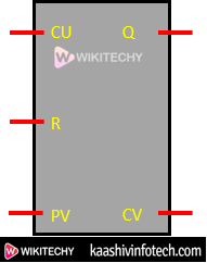
Step-up Counter
- The parameters of the functional block are discussed below:
- CU : It determines the input state of the counter.
- R : It means RESET. it's defined because the reset signal of the counter.
- PV : it's defined because the limit of the counter.
- Q : It means Output.
- CV : it's defined because the current counter value.
- The count value within the counter is represented as C # 10. The counter will count serially till 10 pulses.
How it works ?
- Each pulse on the input of the counter will increase its current value by 1. The output (Q) comes within the SET state when the present counter value is equal or greater than the counter limit.
- A pulse on the Reset (R) will reset the state of the counter. It means the present counter value of the counter will become 0.
Step-down Counter
- The down-counter is used for counting down.
- The functional block of the down-counter will appear as the figure shown below:
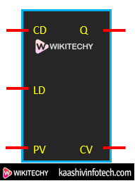
Step-down Counter
- The parameters of the block are discussed below:
- CD : It determines the input state of the down counter.
- LD : It's called the load input.
- PV : PV means the limit of the counter.
- Q : It means Output.
- CV : It's defined as the current counter value.
How does it work?
- Each pulse on the input of the down-counter will decrease its current value by 1. It means the counter value will decrement by 1. The output (Q) comes within the SET state when the present counter value is equal or but 0.
- A pulse on the load input (LD) determines the counter limit value (PV). The value of the counter limit is further assigned to the CV (current counter value).
Step-up-down Counter
- The up-down counter are often used for counting in both ways. we will set the up and down limit of an equivalent number using the up-down counter.
- The functional block of the up-down counter will appear as the figure shown below:
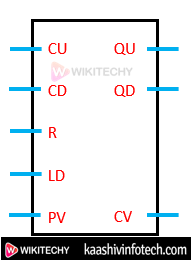
Step-up-down Counter
- The parameters of the block are discussed below:
- CU : It determines the input state of the up counter.
- CD : It determines the input state of the down counter.
- R : It means RESET. It's defined as the reset signal of the counter.
- LD : It's called the load input of the down counter.
- PV : It's defined as the limit of the counter.
- QU : It means Output of the Up counter.
- QD : It means Output of the Down counter.
- CV : It's defined as the current counter value.
How does it work ?
- Each pulse on the input of the up-counter will increase its current value by 1. Each pulse on the input of the down counter will decrease its current value by 1.
- The output (QU) comes within the SET state when the present counter value is bigger or equal than the counter limit (PV). The output (QD) comes within the SET state when the present counter value is equal or but 0.
- A pulse on the Reset (R) will reset the state of the counter. It means the present counter value of the counter will become 0.
- A pulse on the load input (LD) determines the counter limit value (PV). The value of the counter limit is further assigned to the CV (current counter value).
Comparators
- The comparators are used to compare two values. we will also compare physical quantities like pressure, temperature, etc. using comparators.
- The types of values which will be compared using comparator are equal, greater than, less than, not equal, check the validity, and check invalidity.
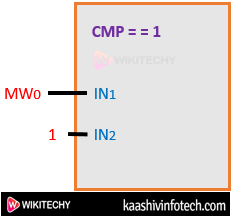
The value in comparators is represented as:
- Equal comparator : CMP = = 1
- Here, one is that the value being compared to. it's wont to determine if the primary value is equal to a second value or not. Similarly, not equal is used to work out if the primary value isn't equal to the second value.
The equal comparator is represented because the figure shown below:
Comparator
- Greater or equal comparator: CMP > = 1
- To determine if the first value is bigger than or adequate to the second value or not.
- Less or equal comparator: CMP <=1
- To determine if the first value is a smaller than or equal to the second value or not.
- Less than comparator: CMP < 1
- To determine if the primary value is a smalle than the second value or not.
- Greater than comparator: CMP > 1
- To determine if the primary value is a smaller than the second value or not.
Examples
Example 1
- We have three pushbuttons. If A, B, and C are pressed, the red LED goes ON. If A and B are pressed, the green LED goes ON. It means that only one LED is on at a time.
Solution
Given
- Here, there are two LEDs : green and red. At a time, one LED light. It can be either green or red.
- Push buttons : A, B, C
We will create a ladder diagram based on the above logic.
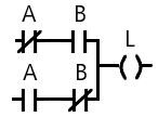
The ladder diagram is shown below:
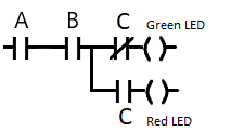
Comparator Ladder Diagram
- Here, we have inserted both NO and NC of the same button 'C' in the ladder diagram. When we press a NO button, it turns NC. When we press NC button, it turns NO.
- When we press the C button, we are pressing both the NO and NC of button C.
Let's start.
Case 1 : Press all A, B, and C buttons together.
- The circuit will now appear as:
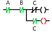
Comparator Circuit
- Here, the red LED will light, as shown above.
Note: The above symbols are colored only for a better understanding.
Case 2 : Press only A and B button
- NC always allows the current to pass through the circuit. It only becomes NO, when we press it.
- The circuit will now appear as:
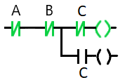
Comparator Circuit
- Here, the green LED will light. Since, the C button was NC, it also allows the current to pass.
Example 2
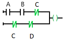
- We have four push buttons. When A, B, and C are pressed, output goes ON. When C and D are pressed, the same output goes ON.
Solution
Given
- Here, there are four pushbuttons: A, B, C, and D.
- But here, we have only one output.
We will create a ladder diagram based on the above logic.
The ladder diagram is shown below:
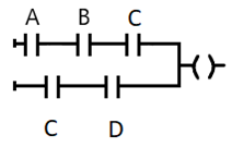
Ladder Diagram of Comparator
- Here, we have used NO (Normally Open) for all the four push buttons. If we want, we can also add NC for the D button in series with the three (A, B, C) push buttons. It will have no change in the output.
Let's start.
Case 1 : Press A, B, and C buttons
- The circuit will now appear as:
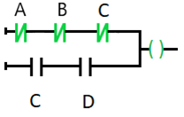
Circuit
Case 2 : Press C and D button
- The circuit will now appear as:
Circuit
- Since A and B push buttons were off, the Output goes ON from the lower series of C and D buttons.
Example 3
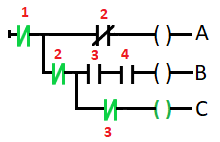
- We have four inputs. Input 1 turns output 'A' ON. Input 1, 2, 3, and 4 turns output 'B' ON, while Input 1 and 2 turns ON output 'C' ON.
Solution
Given
- Here, there are four inputs (1, 2, 3, and 4) and three outputs (A, B, and C).
We will create a ladder diagram based on the above logic.
The ladder diagram is shown below:
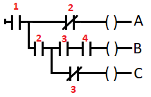
Ladder Diagram of Comparator
Let's start
Case 1 : Press input 1
- The circuit will now appear as:
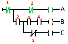
Circuit
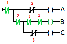
Case 2 : Press all the inputs
- The circuit will now appear as:
Circuit
- We have pressed all the four inputs (1, 2, 3, and 4). Here, output B goes ON.
- As input 2 on the first row and input 3 on the third row is NC. So, pressing them will block the current flow.
Case 3 : Press input 1 and 2
- The circuit will now appear as:
Circuit
- Input 3 is NC. So, it allows the current to reach Output C. Hence; output C goes ON.
Example 4
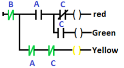
- We have three inputs and three LEDs as an output. When we press button A and B, the red LED turns ON. When we press button A B, and C, the green LED turns ON. When we press button B and C, the yellow LED turns ON.
Solution
Given
- Here, there are three inputs (A, B, and C) and three outputs as LED (Red, Green, and the Yellow).
We will create a ladder diagram based on the above logic.
The ladder diagram is shown below:
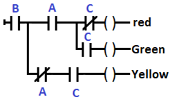
Ladder Diagram
Let's start.
Case 1 : Pressing button A and B
- The circuit will now appear as:
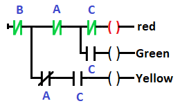
Circuit
- Here, red LED will light.
Case 2 : Pressing all the buttons
- The circuit will now appear as:
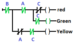
Circuit
- A is an NC button in the third row, which on pressing blocks the current flow. Hence, the Green LED will light.
- We can also insert NC of the B button instead of the A button in the third row. According to the question, we can set the NO and NC as per our choice. But, it should not have any adverse impact on the output.
Case 3 : Pressing button B and C
- The circuit will now appear as:
Circuit
- Now, we will discuss some examples of timers and counters.
Example 5
- There are two motors (1 and 2). Motor 1 becomes ON by pressing the start button. But, when the stop is pressed, it becomes OFF, and Motor 2 is ON for 10 seconds.
Solution
Given
Here, there are two motors. There is the use of time duration in seconds. Hence, timers will be used.
We will create a ladder diagram based on the above logic. The circuit implementation using the timers, etc. It is quite difficult than normal circuits.
Here, we will use the Pulse timer.
We will draw the three ladder diagrams.
The above process is explained step by step.
Let's start
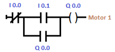
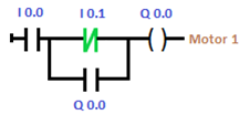
Step 1 : First ladder diagram
The first ladder diagram is shown below:
Ladder Diagram
Here,
'Q 0.0' is the output of the first ladder. The output 'Q 0.0' parallel with the 'I 0.1' button acts as a buffer for the circuit.
'I 0.1' is the start button.
The output of the circuit is considered as the output of Motor 1.
Working
- When we press the start button, Motor 1 becomes ON.
- The circuit after pressing the start button will appear as the image shown below:
Circuit
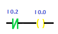
Step 2 : Second ladder diagram
The second ladder diagram is shown below:
Second Ladder Diagram
- 'I 0.2' is the stop button.
Working
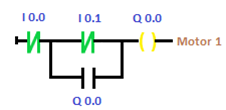
- When we press the 'I 0.2' button, it will turn on the output I 0.0 , which is an NC for the first ladder diagram. The NC 'I 0.0' is a pressed button, which will block the current flow in the first ladder diagram. It will further turn OFF the motor 1.
The circuit after pressing the stop button will appear as:
Circuit
The first ladder diagram appears as:
First Ladder Diagram
Step 3 : Third ladder diagram
The third ladder diagram is shown below:
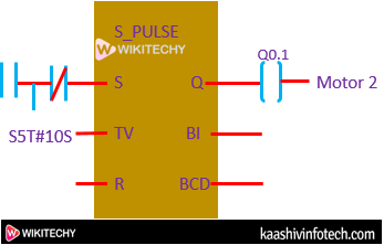
Third Ladder Diagram
- Q 0.1: Output of the Motor 2.
Working
- When we press the 'I 0.2' button, it will turn on pulse timer. The timer will go ON the output Q 0.1. The output will remain ON for the specified duration of 10 seconds. When the counting in the accumulator becomes equal to the Preset value (10), timer stops.
Hence, all the conditions are satisfied according to the question. Similarly, we can create the logic diagram for other questions as well.
Step 4 : Full circuit
The full circuit with three ladder diagrams is shown below:
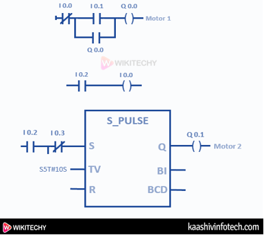
Full Circuit
Automation Tools
- The Automation tools are ANN ( Artificial Neural Network ) , DCS ( Distributed Control System ) , Human Machine Interface , SCADA ( Supervisory Control and Data Acquisition ) , and PLC ( Programmable Logic Controller ).
Let's discuss the most differences between PLC and SCADA.
SCADA
- SCADA or Supervisory Control and Data Acquisition may be a software is used to control and monitor an process accomplished by the PLC. It's generally used for high-level process management systems and analyzing real-time data.
- SCADA is usually used in combination with the PLC, and other devices. The function of SCADA is to control the whole system, while the role of PLC is to act as controller points for specific assets. SCADA includes several components, due to which it possesses greater capability than PLC.
- PLC and SCADA are utilized in the automation industry, like oil and gas, energy, waste control, transportation, water control, etc.
PLC vs. SCADA
| PLC | SCADA |
|---|---|
| It is hardware. | It is software. |
| It comprises CPU, I/O modules, and the peripheral devices. | It comprises of computers, GUI (Graphical User Interface), and networked data communications. |
| It stands for Programmable Logic Controller. | It stands for Supervisory Control and Data Acquisition. |
| It is a system that controls motors and complex machines. | It is a system to run and monitor the plant processes. |
| It is a hardware device that can be of various types, as per the requirements. | It consists of several components that increase its capability. |